Phased Array Ultrasonic Testing (PAUT)
Phased arrays are used for a wide variety of inspection and measurement applications, and they can be used for any job done by conventional ultrasonics. For example, phased arrays are used to detect and image defects including cracks, voids, and pits caused by corrosion. They are used to measure material and coating thickness and to detect changes in material properties. Another common application is to assess the quality of welds and rivets. Phased arrays are also used to inspect joints and interfaces, for example, to detect and map adhesive.
Details
The Basics
Phased array ultrasonic testing (PAUT) probes are composed of several piezoelectric crystals that can transmit/receive independently at different times. To focus the ultrasonic beam, time delays are applied to the elements to create constructive interference of the wavefronts, allowing the energy to be focused at any depth in the test specimen undergoing inspection.
This principle is illustrated in the right picture, where delay laws have been computed to focus the acoustic beam at a specified depth and angle. As shown in the figure, each element radiates a spherical wave at a specified time. The superposition of these wavelets results in an almost planar wavefront at the specified location.
Before and after the targeted focal spot, wavefronts are spherically converging and diverging, respectively. A few examples of delay-law computation are displayed in figure hereunder. When no delay laws are applied, the resulting ultrasonic beam is unfocused and is equivalent to the beam generated by a conventional flat transducer. The natural “pseudo focalization” evident in the image corresponds to the near-field distance of the probe. The configuration illustrated in b results in the same ultrasonic beam that would be generated by a conventional flat transducer used in conjunction with a wedge.
In this case, there is no focusing of the ultrasonic energy; the applied delay laws result in the steering of the ultrasonic beam. Figures c and d are the same configurations as illustrated in a and b, respectively, except that the delay laws have been modified to focus the acoustic energy at a specified depth. In both images (c and d), it is evident that the focal spot is narrower and more localized. To obtain the same results with a conventional probe would require using a specially designed crystal-shaped to obtain the desired focal point.
Ask an Expert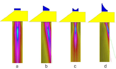
Examples of phased-array ultrasound delay-laws and visualization of the radiated acoustic beam (displacement field). Calculations made using CIVA simulation software: (a) no delay-laws applied, (b) steering only, (c) depth focusing and (d) combined steering and depth focusing.
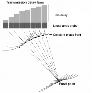
Principle of phased-arrays; delay laws calculated to focus at a given depth and angle
How are phased arrays typically used?
Electronic Scanning
Electronic scanning is a process that reproduces the inspection done by moving manually a standard UT probe. An ultrasonic beam that depends on the aperture selected is electronically translated across the entire probe. This allows for faster inspections and it limits the mechanical displacement. This technique can be combined with beam focusing and beam steering. This can be done using L-wave or S-wave.
Sector Scanning
A sector scan is a process used to control an ultrasonic beam by electronically changing the beam angles within a defined sector. This is done by applying electronic delay laws to the various elements of the array. This technique is an alternative to using several standard UT transducers with different wedges. The advantages are that only one transducer is needed to inspect components under several angles; it is much faster than angled beam standard UT and it displays in real-time a cross-section of the specimen allowing for easier interpretation. This can be combined with electronic focusing and used for L- and S-waves.

Advantage of phased array
Phased arrays have several advantages over conventional ultrasonic probes that derive from the ability to dynamically control the acoustic beam transmitted into the structure under examination.
Phased arrays can reduce inspection times by eliminating or reducing the need for mechanical scanning and by taking advantage of the ability to perform electronic scanning (see animation below). Electronic scanning is accomplished by firing successive groups of elements in the array. Eliminating or reducing mechanical scanning also increases the reliability of the measurements by eliminating changes in (or loss of) coupling, which is a risk each time the probe is moved.
Whereas a conventional probe has one focal length and one orientation, a single phased-array probe allows the user to change the shape and focal point of the ultrasonic beam to optimize each inspection. The acoustic energy can be focused, and delay laws can be applied to steer the acoustic beam. Dynamic-depth focusing allows measurements to be made at several depths in the same amount of time as it takes to a single depth measurement using a conventional probe.
Phased arrays improve the reliability of the measurements and defect sizing can be improved using tools such as sectorial scanning (see figure below), or focalization after reflection off the back wall, two options available with M2M systems. A distinguishing feature of M2M systems is that the user can tune the beam, for example, to define any focal points in a 2S or 3D CAD drawing.
Because of their flexibility, a phased-array probe can replace an entire toolbox of conventional ultrasonic probes. It can thereby simplify complex inspection procedures by eliminating the need for multiple probes, and the associated calibrations and setups. Phased-arrays provide tremendous functionality including real-time imaging.
Compared to measurements with conventional single-element probes, the detection and sizing of defects is much easier and more robust. Instead of struggling to find the optimal single signal that can be obtained with one element, a phased array allows hundreds of signals to be captured at once. The greatly improved efficiency makes it much easier to characterize defects and reduces the number of false alarms. When used in conjunction with simulation, inspection strategies can be optimized to improve detection. Data recording and traceability are also greatly improved. For example, inspection data can be saved and compared to simulated results, helping to confirm whether or not there is a defect in the inspected structure.

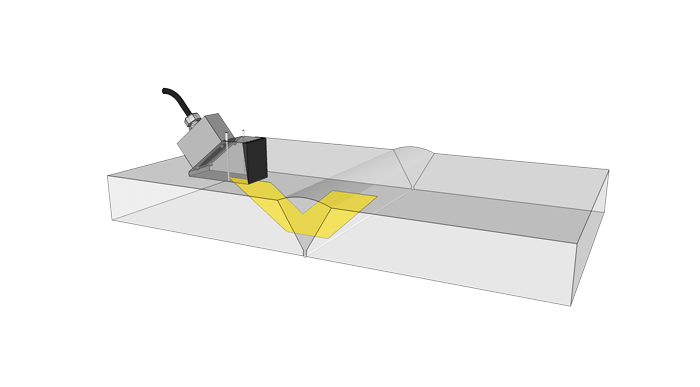
Sectorial scanning 3D beam profile Sectorial scanning combined with focusing. Using CIVA (or the M2M software), the ultrasonic beam can be simulated. The figure shows the radiated field calculated for a 32-element linear array for a specified range in a sectorial scan (longitudinal mode, -30 degrees to +30 degrees). The simulation makes it possible to verify the size and location of the focal spot for every angle. The 3D visualization is displayed above in the specimen geometry, which greatly facilitates the analysis of results.
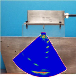
Real-time sectorial-scan imaging using an M2M system and an linear array (64 elements@5MHz). A series of side-drilled holes are evident in the image.
Learn more